
Sheet metal unfolding · STEP → flat blank → DXF
Online sheet metal unfolding from a STEP file — flat DXF blanks.
You drop in the folded part. It comes back down flat, with its developed outline, its holes, its dimensioned bend lines, its radius and its angle. The DXF goes to the cutter, the PDF goes to the press, the part mark points back to its place on the assembly.
Accepted input formats: STEP, IGES, BREP. Output: DXF of the flat blank, dimensioned PDF for the press brake.
Sheet metal unfolding online: from the folded part to the flat blank.
The workflow fits in five steps, of which you drive only one:
- STEP — you drop in the file of the folded part.
- Detection — the software spots the sheet metal part(s) in the assembly.
- Unfolding — each part is laid flat, respecting the radius and angle of every bend.
- Dimensioning — the flat blank is dimensioned: outline, holes, bend lines, radii, angles.
- DXF — the file comes out, one DXF per flat blank, ready for laser or plasma cutting.
All the prior analysis — part recognition, profile/sheet-metal separation — is done by the same STEP analysis pass. You will not sort parts by hand.
What the flat blank carries
Three pieces of information, not a drawing more.
Developed outline
The perimeter of the sheet laid flat, with holes in position. This is what the laser or plasma head will follow. The outline carries the file’s scale — no adjustment to make before sending to the machine.
Dimensioned bend lines
Every bend is drawn as a dashed line on the flat blank, with its angle and its radius. This is what the press brake operator will read to set the tool and check that the part comes out to spec.
Part mark back to the assembly
The flat blank keeps its part reference — the one from the assembly drawing. Coming off the press, you know which frame the part will bolt onto: no stray sheet metal with no origin.
The flat blank, seen from the press
One folded part, two DXF flat blanks ready.
The 3D assembly in the center, left and right the “flat blank” windows with the developed outline, the holes, the bend line dimensioned at 94° and a 9 mm radius on 4 mm sheet.
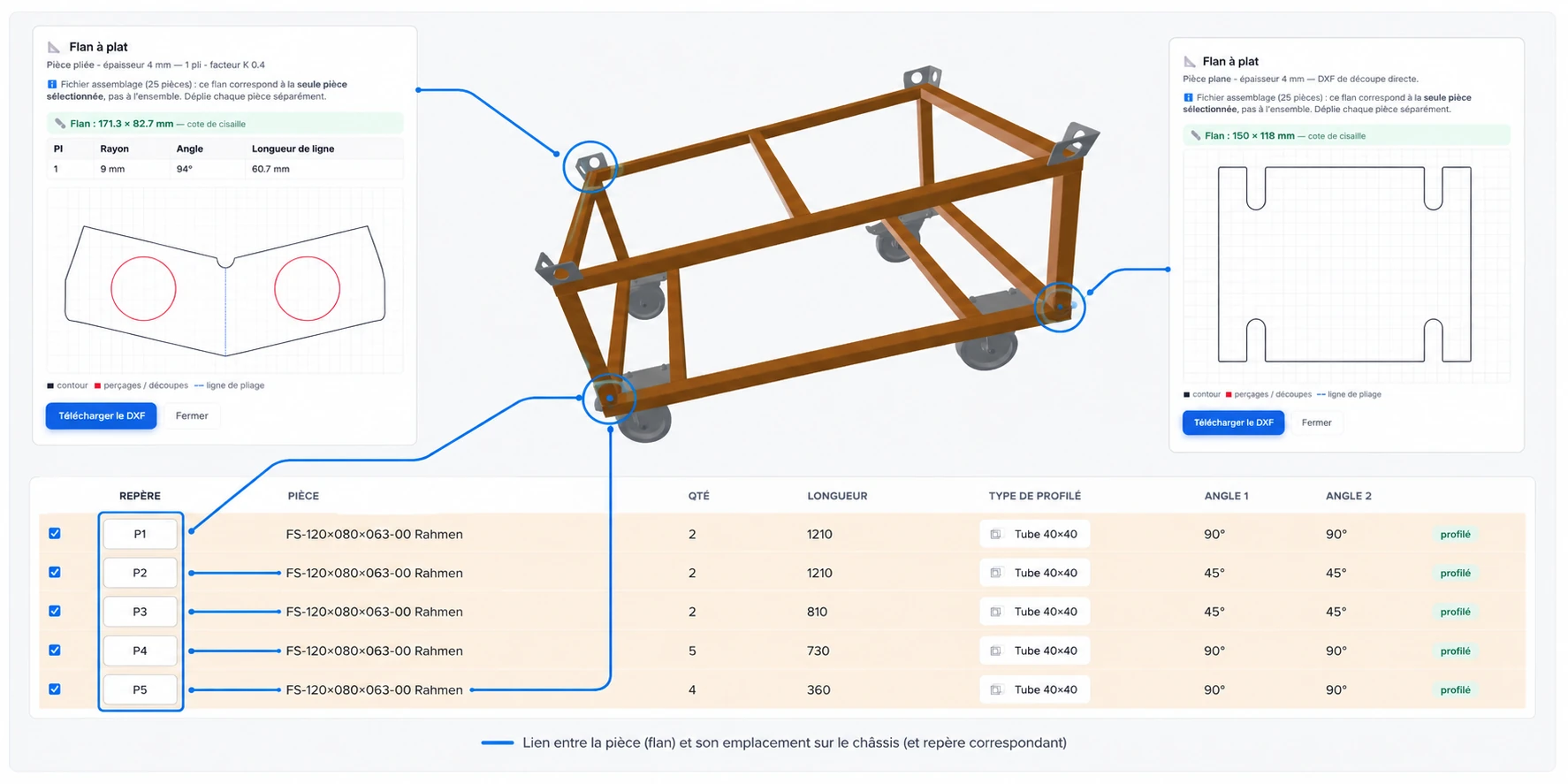
STEP to DXF, in one drop.
The STEP to DXF conversion of a sheet metal part is not a magic export: the part has to be unfolded before it can be shown flat. That is what Cut to Fab does automatically — the STEP goes in folded, the DXF comes out flat, dimensioned and ready to cut.
This conversion applies only to folded sheet metal parts. A solid part or a profile does not go through unfolding: for those, the relevant DXF is the cutting outline, produced by the bar nesting.
Cases handled — and cases where the software flags itself.
The unfolding engine is a geometry engine — not an AI that guesses. It cleanly unfolds parts where every bend is identifiable: a constant-angle fold, a defined radius, uniform material thickness. That covers the bulk of structural and architectural metalwork sheet metal.
Some geometries go beyond its scope:
- the stampings and doubly curved parts — flat unfolding has no unique solution;
- sheets with variable thickness;
- certain parts fused to others in the STEP (the solid combines several bodies).
In those cases, the part is flagged, not silently unfolded onto a wrong flat blank. You see the reason for the failure and can enter the flat-blank dimensions by hand or draw the DXF outline in your own CAD software.
Where the unfolding runs.
The unfolding is the only Cut to Fab computation that runs on our servers. The reason is technical: it relies on a geometry engine (FreeCAD) that we cannot embed in a browser tab — it weighs several hundred megabytes and requires a native stack. Running it server-side lets us return the result in a few seconds, even on a modest workstation.
Concretely: when you click “unfold”, the geometry of the relevant part leaves encrypted in transit. The flat blank comes back down. We keep nothing after the computation, and this step is shown on the screen so that you know before clicking that the file is about to leave your machine.
Frequently asked questions on unfolding
What we get asked before clicking “unfold”.
Is the flat blank at the correct developed length?
Yes: the computation follows the standard K factor of the geometry engine, adjusted for the radius and thickness of each bend. It is the value accepted by the trade for everyday steel and aluminum sheet metal. For unusual materials or radii, it is still recommended to check the first part off the press — as with any unfolding software.
Can I adjust the K factor or springback?
Not yet through the interface: the engine currently applies its standard K factor, with no on-screen field to force it per part or per material. That configuration is planned for a future version. If you have a specific need (special material, badly calibrated press that needs compensation), write to us — we quantify the offset and take it into account.
Does my STEP file go to a server?
The geometry of the part to be unfolded, yes — it is the only remote computation of the software. The STEP read and the 3D view stay local: you see and check the part in your browser before requesting the unfolding. Nothing is kept on the server side beyond the computation, and the screen warns you before sending.
Which thickness, which materials?
The engine is not limited to any particular thickness or grade — it works from the STEP geometry. In practice, structural and architectural metalwork sheet metal (steel, stainless, aluminum, thicknesses roughly 0.5 to 6 mm) goes through with no configuration. Beyond that, a workshop check remains advisable.
Is unfolding included in the Free plan?
Yes, with a reasonable per-day file limit — enough to help out and to try on a small job. Beyond that, the Pro plan lifts the limit. The tier details are on the pricing.
What is sheet metal unfolding?
Unfolding — also called flat pattern calculation, laid flat or development — is the task of representing a folded sheet metal part as if it had been laid flat. You then get back its developed outline (the one the laser cutter will follow), the position of its holes, and the dimensioned bend lines with their radius and their angle. It is the essential step to go from a 3D part to a DXF flat blank usable in the workshop. Cut to Fab computes this automatically from a STEP file.
Can Cut to Fab convert a STEP file to DXF?
Yes, for folded sheet metal parts : that is exactly what the unfolding does. You drop in the STEP, the part is laid flat, and the DXF of its developed blank comes out — ready for laser or plasma cutting. For profiles and solid parts, the relevant STEP → DXF conversion is the cutting outline, produced by bar nesting.
Who is Cut to Fab’s unfolding for?
To workshops in structural and architectural metalwork, boilermaking and welded assembly, which receive STEP files from the design office and need to produce the DXF flat blanks of their folded parts without going back through a CAD software. Typical case: a wheeled frame, a hopper, an enclosure — the structure carries folded sheet metal parts, and their dimensioned flat blank has to come out for cutting and the press brake.
In the same software
What else Cut to Fab does.
Bar nesting
The cut list laid out bar by bar, with paired miter cuts and reusable offcuts.
STEP analysis
The profiles of an assembly recognized and measured, with nothing to retype.
Comparison
What general-purpose cutting tools do not do: angles, paired miters, offcuts, STEP.
Send in your first part.
The Free plan accepts STEP import and unfolding. If the flat blank that comes out does not match your part, you know in five minutes — and you paid nothing to find out.