
STEP import · fabrication preparation
Automatic STEP file analysis for fabrication.
You drop in the 3D assembly from the design office. The profiles are recognized, measured, listed with both of their cut angles. The sheet metal parts are unfolded flat, dimensioned, ready as DXF. Every part keeps its part mark pointing back to its place on the frame.
Accepted formats: STEP (.step, .stp), IGES, BREP. Typical assembly size up to several hundred parts.
The STEP comes in heavy. The cut list has to come out light.
A STEP file describes a 3D assembly — geometry, hierarchy, sometimes a bill of materials. Opened in a viewer, it looks nice. Opened with the intent to manufacture, it says nothing on its own: the 40×40 square tube is represented by surfaces and edges there, not by a row in a cut list. It has to be re-read.
That is what the analysis does: recovering, for each part, what matters to produce it. The length of a profile section, its two cut angles, its cross-section — to head to the saw. The outline of a folded part laid flat, its holes, its bend lines — to head to the cutter and the press.
What is extracted
STEP tube nesting: profiles and sheet metal from one drop.
Profile recognition
Square, rectangular and round tubes, along with standard angles and flat bars, are identified from their cross-section and axis. Length, two cut angles and profile reference come out in the cut list — without re-entering them from the paper drawing.
Sheet metal unfolding
A folded sheet metal part is laid flat: you get back its developed outline, its holes, its dimensioned bend lines and the radius used. The flat blank comes out as DXF, ready for laser or plasma cutting.
Every part marked
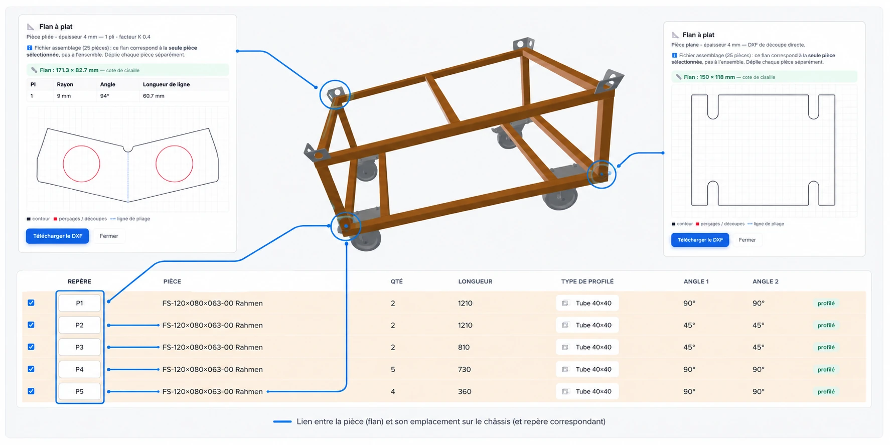
Every cut part and every flat blank keeps a part mark pointing to its place in the assembly. On the wheeled frame, you know which tube goes where, and which folded part sits on which crossmember — no need to re-open the drawing to check.
Seen from the workshop
One frame, five cut parts and two flat blanks, in one drop.
The 3D assembly in the center, two “flat blank” windows on the left and right with their dimensions and bend angles, the cut list at the bottom — profile, length, angles, quantity. Each flat blank is linked to its part on the frame and to its row in the table.
Where the computation runs.
The STEP read and the 3D view happen in your browser — the file does not leave your machine until you explicitly ask for a remote operation. That is the part that handles large assemblies locally, and keeps working during an Internet outage.
The profile recognition also runs mainly in your browser. The sheet metal unfolding, however, is sent to our servers: it relies on a geometry engine (FreeCAD) that we cannot embed in a browser tab. The part to be unfolded leaves encrypted in transit, the flat blank comes back down, and nothing is kept on the server side beyond the computation.
This split is shown on the screen at the moment of the action: you never click “unfold” without knowing that the file is leaving. That is the principle we will keep for every server-side feature to come.
What stays manual — and why we own it.
Profile recognition is not 100 %, and we prefer to write it. Exotic profiles (in-house extrusions, non-standard sections), warped tubes, or assemblies where several parts are merged into a single solid sometimes fail to be recognized. In that case, a panel flags the unidentified part and offers manual entry: you correct its cross-section and its reference, and it joins the cut list.
The failure rate drops with each version — it is one of the product’s ongoing workstreams. We prefer software that recognizes 90 % of cases and knows how to say “this one, over to you” rather than software that guesses and puts a wrong-section tube into your cut list.
Frequently asked questions on STEP analysis
What we get asked before dropping in a file.
Does my STEP file go to a server when it is read?
No for the reading, the 3D view and the profile recognition: everything runs in your browser. The file only goes to our servers if you explicitly request the unfolding of a sheet metal part, and the screen tells you so at that moment. Nothing is kept after the computation.
Which profiles are recognized?
The square and rectangular tubes, the round tubes, the angle profiles and the flat bars with standardized sections. Special profiles (in-house extrusions, non-standard sections) are not always recognized: in that case, the part is flagged and you correct it manually.
What assembly size can the software handle?
Several hundred parts in practice. Reading STEP in the browser uses memory in proportion to the geometry: on a machine with 8 GB of RAM, large light-frame chassis go through; beyond that, we prefer splitting the file rather than promising magic.
Do I get the assembly bill of materials?
Yes: the recognized cut list is an exportable CSV, each row carrying the part mark, its profile, its length, its two angles and its quantity. Sheet metal flat blanks come out as DXF, one file per part.
Do I need a paid plan to use the STEP analysis?
No for reading, the 3D view and single-part DXF export: these features work from the Free plan onwards. The Free plan limits are on the number of saved projects (2 without an account, 5 with a verified account) and on the number of cut parts in a cutting plan (30 per calculation without an account, 50 per project with a verified account), not on the size of the imported STEP. The details are on the pricing.
What is a STEP file?
A STEP (extension .step or .stp, ISO 10303 standard) is the standard exchange format for 3D CAD in industry. It describes an assembly — geometry, part hierarchy, sometimes a bill of materials — in a way readable by every major CAD software (SolidWorks, Inventor, Fusion 360, Onshape, FreeCAD, TopSolid…). It is the file your design office hands over when moving from drawing to fabrication.
Can Cut to Fab read an IGES or BREP file?
Yes. Cut to Fab accepts as input the formats STEP (.step, .stp), IGES (.iges, .igs) and BREP, which cover the bulk of 3D CAD exports. The reading is done in your browser — no install, no prior conversion required.
Does Cut to Fab replace my CAD software?
No. Cut to Fab reads the STEP file produced by your CAD software and converts it into a cut list and DXF flat blanks for fabrication — it replaces neither drawing nor modeling. You keep drawing with the tool you know; Cut to Fab slots in between CAD and the workshop, without forcing you to change your upstream habits.
In the same software
What else Cut to Fab does.
Bar nesting
The cut list laid out bar by bar, with paired miter cuts and reusable offcuts.
Sheet metal unfolding
The dimensioned flat blank, with its bend lines, as a DXF for cutting.
Comparison
What general-purpose cutting tools do not do: angles, paired miters, offcuts, STEP.
Drop in your STEP, judge on the list that comes out.
The Free plan accepts STEP import with no size limit. If the cut parts come out wrong or the recognition fails on your profiles, the price paid is zero and you know in five minutes.